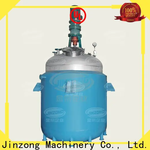
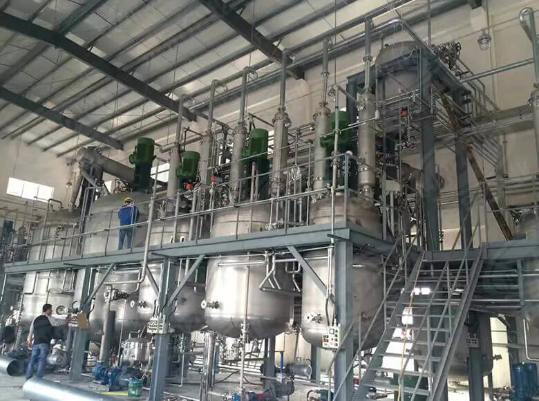
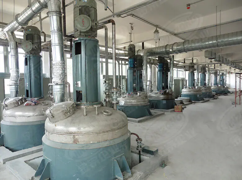
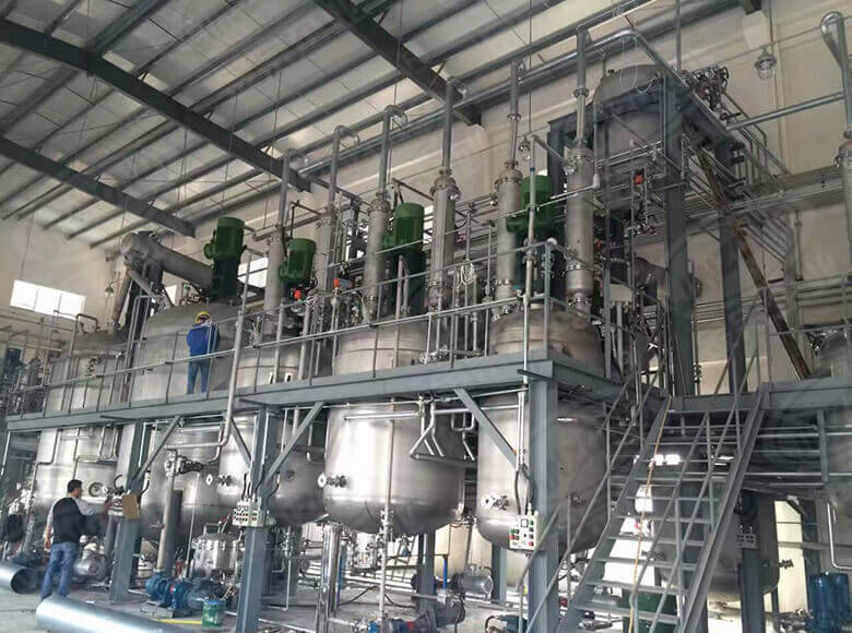
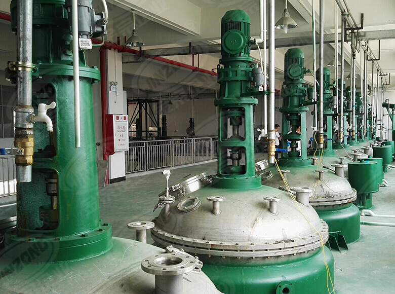
The reactor is an important equipment used in chemical, pharmaceutical, food and other industries for chemical or physical reactions. Its performance directly affects the quality of products and the safety of production. Therefore, it is very necessary to regularly overhaul the reactor and ensure that it meets certain quality standards. Next, Jin Zong Enterprise, which has more than 20 years of experience in reactor research and development, design and manufacturing, will introduce in detail the overhaul method of the reactor and its related quality standards.Kettle body
1. Replacement conditions
The reaction kettle should be replaced if it has been for a certain number of years and one of the following conditions occurs:
a. The wall thickness of the kettle body is uniformly corroded and exceeds the minimum value specified the design;
b. The wall thickness of the kettle body is locally corroded and exceeds the minimum value specified in the design, and the corroded area is greater 20% of the total area;
c. During the hydrostatic test, the equipment has obvious deformation or residual deformation exceeds the specified value;
d. to alkali embrittlement or intergranular corrosion, cracks occur in the kettle body or welds and cannot be repaired;
e. When the damaged area the porcelain surface exceeds 15% or the damaged part cannot be repaired;
f. When there are defects that exceed the standard (such as: serious structural defects endanger safe operation; welds that do not meet the requirements; serious incomplete penetration, cracks, etc.) and cannot be repaired.
2. Steel kettle body
a. Local corrosion of the shell shall be repaired by arc welding method, and if the corroded area is large, the patch method shall be used for repair.
. Unthreaded cracks. If the depth of the crack is less than 10% of the wall thickness and not more than 1mm, the crack can be flat with a grinding wheel, and it is smooth transition with the metal surface. If the depth of the crack does not exceed 40% of the wall thickness, a be can be chipped out within the depth of the crack, and then it can be welded, but it is better to drill small holes at both ends of the crack to prevent crack from extending. For long cracks, the method of welding from both ends of the crack to the middle should be used (from both ends of the crack to the middle) to the welding stress and deformation. If the depth of the crack exceeds 40% of the wall thickness, it should be treated as a penetrating narrow crack.
c Penetrating narrow cracks. Before welding, drill stop holes at both ends of the crack, the hole diameter is slightly larger than the crack width, and the bevel is processed When the wall thickness is less than 12mm, the V-shaped bevel is adopted; when the wall thickness is greater than 12mm, the X- bevel is adopted. During welding, cracks less than 100mm can be welded at one time; when the crack is longer, it is better to weld both ends of the crack to the middle, not to draw a circle, and to use multi-layer welding. Except for the parts with stress concentration, cracks and penetrating narrow on the kettle body are allowed to be repaired.
d. Penetrating wide cracks. Wide cracks should be repaired by digging. The length of the dug part should 50 ~ 100mm larger than the length of the crack, and the width should not be less than 250mm. The welded patch should be with the surface of the main body, and the radius of curvature should be the same as that of the main body.
e. Stainless steel lining bulge. When lining is deformed on a large area and the height of the lining bulge is less than 0.15 times the average diameter of the deformed area, it is advisable to use water filling pressure method to restore the deformed lining. For shells or linings with small deformation area, mechanical top pressure method can be used for repair, but attention should be paid prevent brittle cracking during the correction process.3. Cast iron kettle body
For common defects of cast iron kettle body such as sand holes, cracks, p corrosion or local corrosion, arc cold welding is usually used for repair. When welding, one stop-crack through hole should be drilled at 3-5mm away from each end the crack.
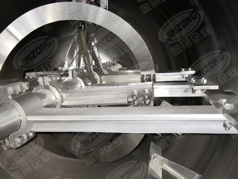
4. Lining glass kettle body
Lining glass is brittle and easy to damage, and has poor thermal stability. During maintenance, it necessary to pay attention to the protection of the porcelain surface. It is required to hang or tie the lifting ring or rope at the designated position. Necessary cooling measures should taken during welding. The following repair methods can be used respectively according to different damage conditions.
a. Corrosion-resistant metal plugging method. When there are micores on the porcelain surface, corrosion-resistant metal materials can be made into plugs and directly driven into the micropores.
b. When the damage of porcelain is slightly larger, corrosion-resistant metal bolts and corrosion-resistant material gaskets are used to fasten the damaged porcelain surface.
c. Inorganic coating repair. The surface to be repaired should be cleaned, rusted with 15-20% dilute sulfuric acid, then neutralized with 10% caust soda solution, then washed with water, wiped clean, dried with hot air, and finally inorganic paint is recoated and slowly heated and cured. The weight ratio of the is: flint rock powder: 100, fineness 80-100 mesh; sodium silicate: 5, purity > 95%; glass: 95, specific gravity 1.48.
d. Organic coating repair method. The same as inorganic coating repair method.
Organic coating weight ratio:
Epoxy resin: 100
Dibutyl phthalate: 15
M-phenylenediamine: 2~14
Graphite (or other filler): 50~100.
After coating, heat treatment should be carried out at a temperature of80~100℃. The temperature should be slowly increased during heating, and it can be used after full curing.
e. The number of clamping for the flange of lining glass kettle body must be kept to the specified standard and evenly distributed. The clamping clips must be symmetrically and evenly tightened along the diagonal, not too much force or once tightened.5. Quality standards for the repair of the kettle body
a. The weld and the base metal should have a smooth.
b. The depth of local undercut on the weld should not exceed 0.5mm, and the length of the undercut connection should not exceed100mm.
c. The weld should be free of cracks, incomplete penetration, incomplete fusion, slag inclusion, and porosity.
. The slag and spatter on the weld should be cleaned up.
e. After repair, no cross welds should appear, and the longitudinal seams between cylinders and between the head and the adjacent cylinder should be staggered, with a spacing greater than three times the thickness of the cylinder and not less than 100mm.
f. The rework of the weld should not exceed twice.
g. The correct material for the electrode should be selected, and the electrode and flux be dried and used as soon as possible.
h. The kettle body after welding must undergo a hydraulic strength test.
When performing the hydraulic strength test the air in the kettle should be completely purged, and the pressure should be slowly increased when the temperature of the kettle wall is close to the temperature of the liquid. pressure should be maintained for 10-30 minutes under the test pressure, and then reduced to the maximum working pressure for inspection. The test is considered successful if there is leakage, no visible abnormal deformation, and no abnormal noise during the test. For kettles with external insulation or those whose appearance cannot be observed, the test should be maintained at maximum working pressure for at least 2 hours, and the test is considered successful if the pressure does not drop and there is no abnormal noise.
i. For kles that require a gas tightness test, the test should be performed after the hydraulic test is successful, and the temperature of the test gas should not be lower than 5℃.Transmission device
Triangular belt drive
a. When installing and aligning the pulleys, theism of the two pulley axes shall not exceed 0.01a, and the axial displacement of the two wheels' width symmetry plane shall not exceed 0.05a (a is the actual center distance of the two wheels, unit: mm).
b. For the fit between the pulley hole and the shaft, H7k6 is selected, and the surface roughness is selected as 1.6/0.8.
c. The tension of the triangular belt should be uniform and.
d. The pulley should be replaced when there are cracks in the pulley hole, notches in the pulley groove, or serious wear on the groove surface
e. The triangular belt should be replaced in case of serious wear; contact between the belt and the bottom of the groove; belt aging; cracks; plastic distortion.
f. The triangular belts on the same pulley should be replaced at the same time.
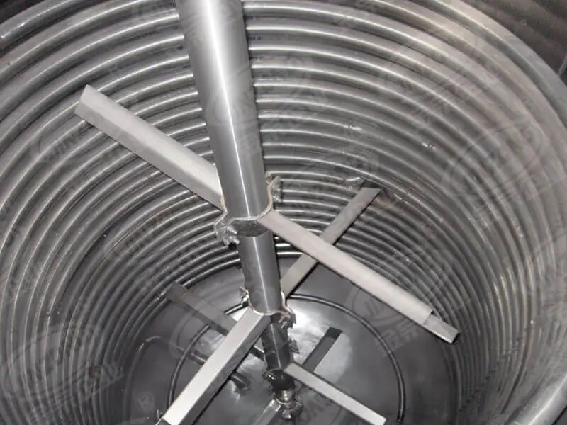
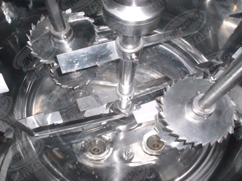
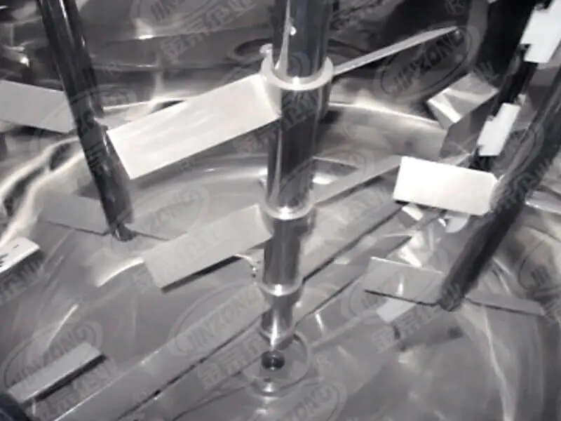
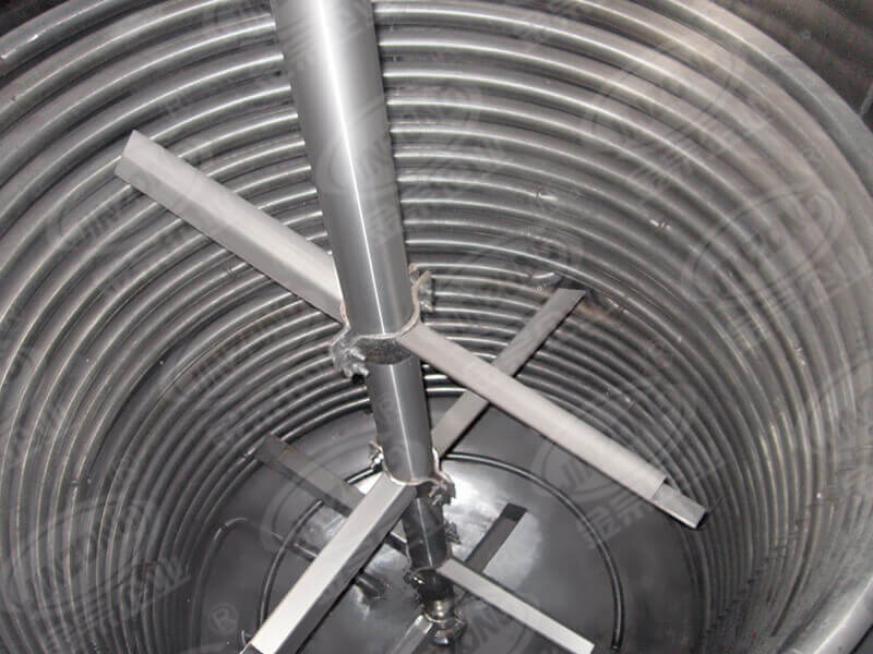
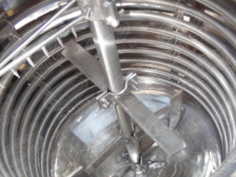
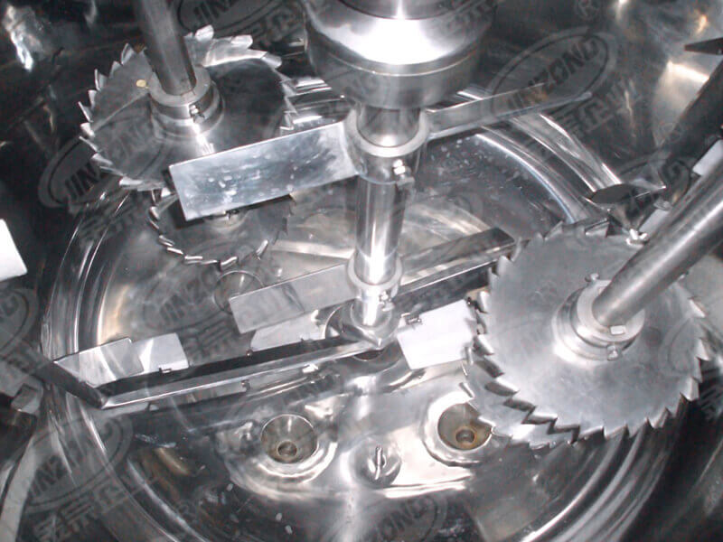
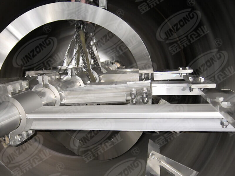
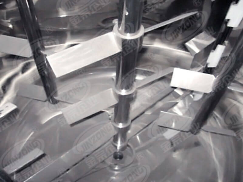
Mixing device
a. When the mixing shaft is bent, it can be straightened by mechanical pressure method, the straightness of the mixing shaft is 0.10mm/m, and the straightness of the shaft diameter position is .04mm/m.
b. When the mixing shaft and the sealing filler are worn, they need to be micro-machined to round, and if the amount is greater than 0.5mm, they should be welded and then machined to restore the dimensions of the drawing. Surface roughness 0.8.
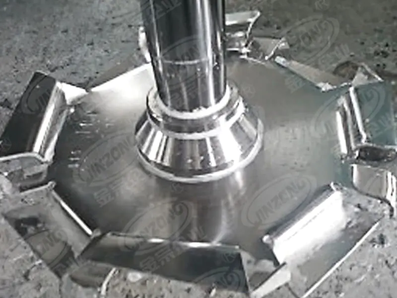
c. The mixing blade should be replaced when it is evenly corroded more than 30% of the original thickness.
d. For local corrosion, cracks, and of the mixing blade, use welding, shaping, and correction methods for repair. When the enamel mixing blade is damaged by corrosion, chipping, etc., it should be according to the enamel repair method.
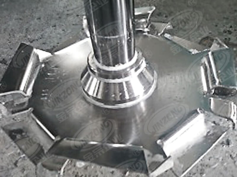
e. The axis of the paddle, frame, and anchor mixing blades should be perpendicular to the blade, with a perpendicularity of4/1000 of the total length of the blade, and should not exceed 5mm.
f. The turbine and propeller mixing blades with a speed than 100r/min should be tested for static balance. Dynamic balance can be achieved by either weight removal or weight addition method, and the thickness of the cut or part should not exceed 1/4 of the wall thickness, and the transition at the junction should be smooth. When the speed is less than 500r/min the unbalanced mass on the outer diameter of the impeller should not exceed 20g.
g. For the turbine and propeller mixing blades, the blade hole the mixing shaft neck are selected with H7/k6 fit, and the surface roughness is selected as 1.6/0.8.
h. The rolling are disassembled with special tools, and the oil temperature is 140℃ when they are hot-fitted. It is strictly prohibited to heat directly with flame.
i. When installing the rolling bearing at the lower end of the mixing shaft, the outer ring should not be pressed to death, and there should be about 0.5-.0mm of axial thermal expansion and contraction allowance.
j. The rolling elements and the surface of the raceway of the rolling bearings should be free of corrosion, pits spots, and contact should be smooth without noise. The shaft neck that fits with the inner hole of the rolling bearing is selected with k6, and the surface roughness is .8, and the hole that fits with the outer ring of the rolling bearing is selected with K7, and the surface roughness is 1.6.Axial Sealing Device
1. Stuffing Box Sealing
a. The fit between the stuffing box cover the stuffing box body is H11/d11, and the clearance between the cover hole and the shaft is 0.75-1.00mm (aft diameter 50-110mm), and the clearance between the agitator shaft and the body is 0.60-1.00mmshaft diameter 50-110mm).
b. The end face clearance between the stuffing box cover and the body should be equal, and the error not exceed 0.3mm.
c. The material and specification of the packing should be used correctly, with moderate length and width, and the lap joint of each of packing should be evenly staggered along the circumferential direction, with a lap joint angle of 30°, a flat cut surface, and the upper and lower parts be aligned.
d. The packing should be left with appropriate margin for compression.
e. The position of the oil ring should be accurate, and the oil passage be unobstructed.
2. Mechanical Seal
a. The perpendicularity between the shaft and the sealing cavity is generally 0.05mm, and coaxiality with the sealing cavity is generally 0.5mm, the radial jump is 1mm, and the axial displacement is 1mm.
b. The roughness of the shaft at the installation position of the mechanical seal should not be lower than 1.6.
c. The sealing cavity should be kept clean, and surface roughness of the sealing surface of the dynamic and static rings should not be lower than 0.2, and it should not leak when filled with water.
d The adjustment of the end pressure ratio should be appropriate, to ensure good lubrication and minimize leakage. Keep the sealing surface in a semi-liquid friction state.
e. direction of the spring should be consistent with the working direction of the shaft.
f. The perpendicularity of the static ring end face to the axis should not be greater than0.05mm.
g. The dynamic ring of the installed mechanical seal should operate flexibly and reliably.
h. When turning by hand, the sealing should turn smoothly without any abnormal phenomena.
i. The air tightness test is qualified if no continuous small air bubbles are produced.
Safety Accessories
afety valves, burst discs, and pressure gauges shall be carried out in accordance with the relevant provisions for pressure vessels.
Liquid Level Gauge
Before installation use, the liquid level gauge should be subjected to a hydrostatic test at 1.5 times the nominal pressure of the liquid level gauge.
The liquid level gauge should stopped and repaired or replaced under any of the following conditions:
a. Exceeding the inspection cycle;
b. The glass plate (tube) has cracks or;
c. The valve is stuck;
d. False liquid level often occurs.
Other instruments, signal interlocking, safety devices, etc., should carried out in accordance with the relevant provisions.Installation
a. The allowable horizontal error for the installation of the kettle body is 1mm/m.
b. The allowable error for the installation elevation of the kettle body is ±5mm, and the allowable error for the position of the meridian and latitude:
When the diameter is less than 1m, it is ±5mm;
When the diameter is greater than 1m, it is ±8mm.
. The distance between the pressure pipe, thermometer sleeve, heating coil, and the agitator shall not be less than 40mm.
d. The deviation between two flanges should be less than 1mm, and the distance between the flange faces should be less than 2mm. Only one gasket is allowed between twoanges, and it is not allowed to use multiple gaskets to eliminate the defect of excessive distance between flange faces.
e. The flange sealing surface shall be and free of mechanical damage, radial scratches, severe rust, weld scars, and residue of materials. The manhole cover plate shall be free of obvious deformation, rust, cracks and other defects.
f. The sealing gasket must be installed correctly and coated with a thin layer of scaly graphite paint on both surfaces of the gasket.
g. The nut on the bolt should rotate flexibly but not shake, and the thread should be clean. When tightening the flange, it is required to use a torque to tighten symmetrically and evenly in two to three times. The tightening force should not be excessive, insufficient, or uneven.
h. It is not allowed to use bolts different materials and specifications on the same flange.
i. For bolts that need to be tightened or cold tightened during the process of temperature rise or fall, the regulations must be followed.
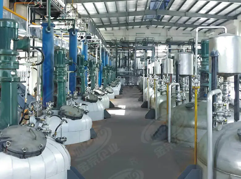
The reactor, as one of the key equipment in industrial production, its stable operation is essential. Through detailed inspection of the reactor and strict ad to various quality standards, not only can the product quality be guaranteed but also the service life of the equipment can be effectively extended, reducing the loss of downtime due to faults. Enter should formulate detailed maintenance plans, regularly carry out comprehensive inspections of the reactor, and ensure that the equipment is always in the best working condition.
Read More>>


 CE Certificate
 ISO9001:2015
 SGS
SGS
